Electronics Training Module
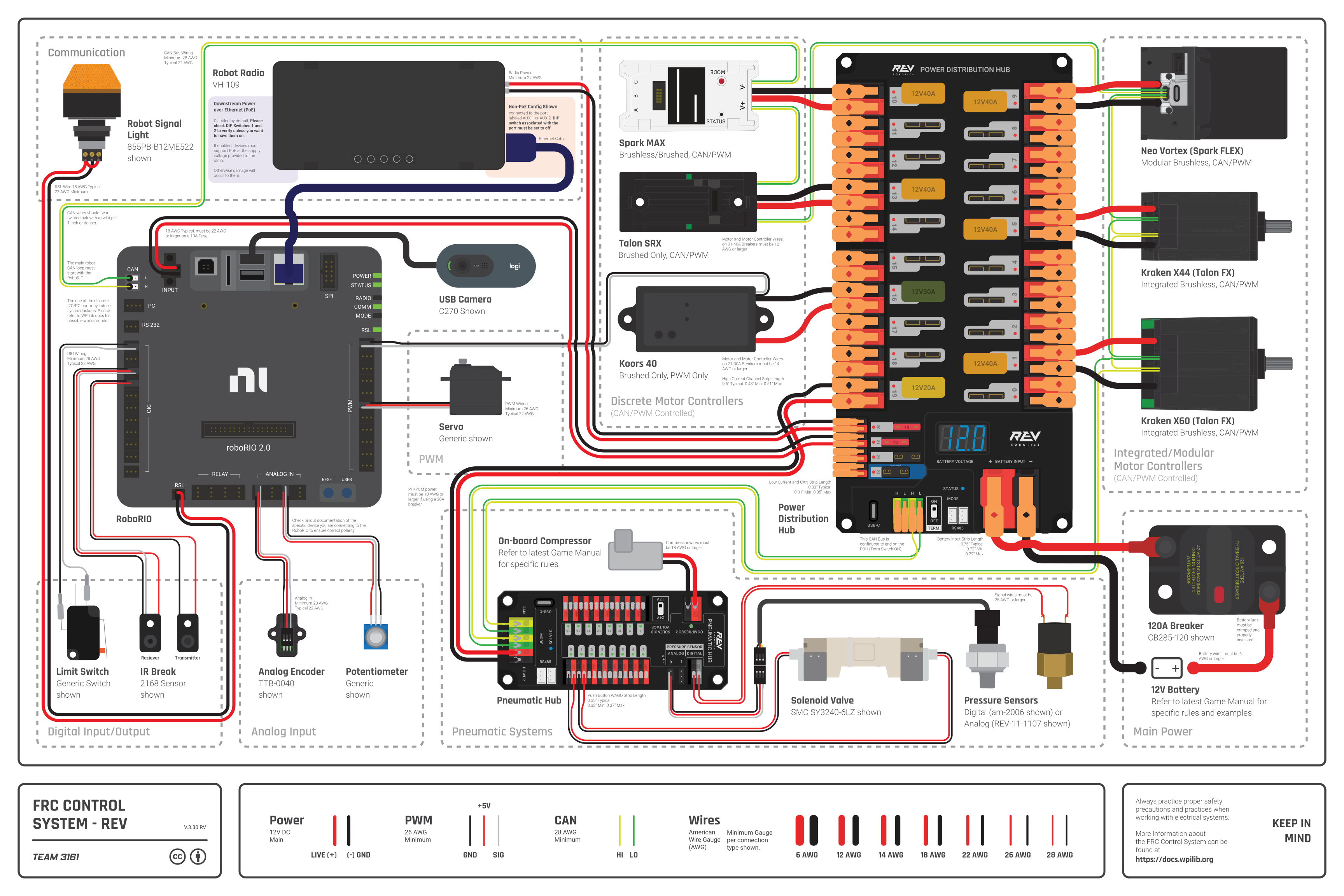
Above is an example of a fully wired FRC robot system. This module will take you through all the major components and the basics of wiring.
Click a component to learn more.
Image sources: REV Robotics, AndyMark, WPILib, CTR Electronics
Drag each component image from the left into the correct definition box.
Component Images
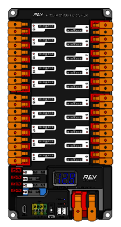
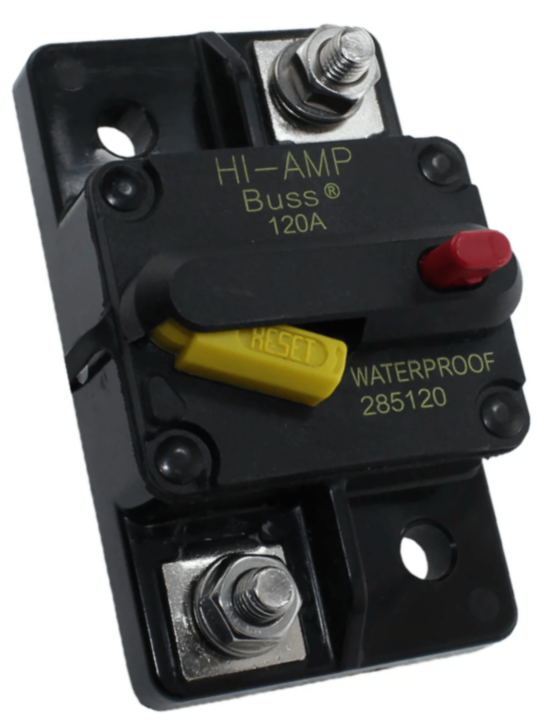
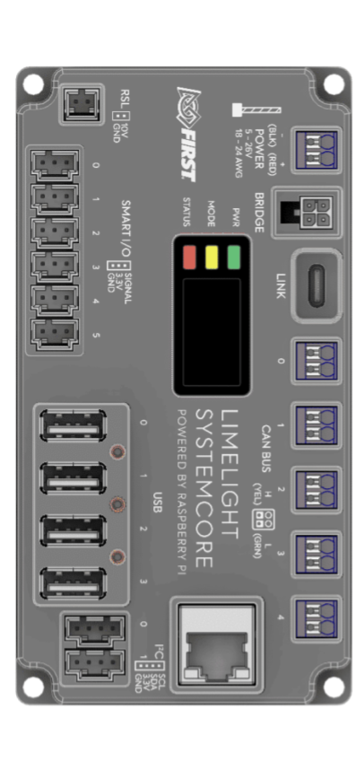
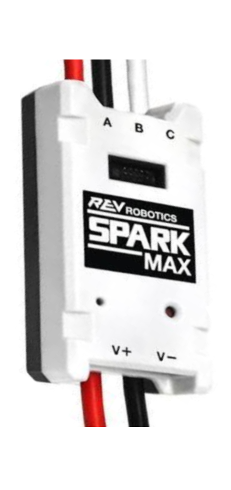
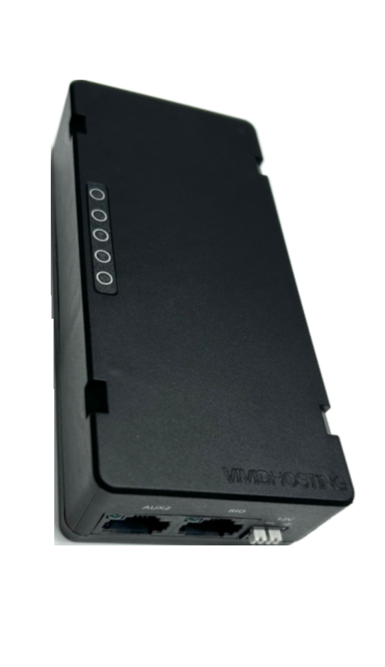
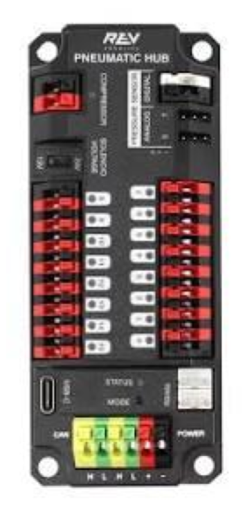
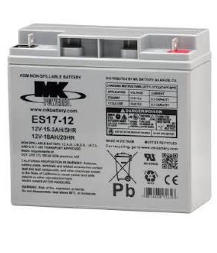
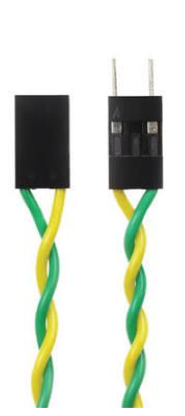
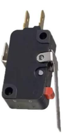
Definitions
Sends power to circuits through breakers.
Robot's primary power shutoff.
Main robot controller.
Controls power to motors.
Connects robot to field and Driver Station.
Controls compressor and solenoids.
Main robot power source.
Onboard communication network.
Encoders, limit switches, gyros, cameras, etc.
Mount parts where they can survive and be serviced
Protected
Keep electronics away from direct impact zones, game pieces, metal chips, and moving mechanisms.
Accessible
Leave room for hands, tools, connectors, status lights, and replacement parts.
Firmly Mounted
Use a belly pan or electronics panel with bolts, rivets, or strong mounting hardware.
A clean robot is not the same as a reliable robot. Reliability comes from secure mounting, protected routing, good connections, and clear documentation.
Do
- Use a dedicated electronics panel or belly pan.
- Use bolts, rivets, or strong mounting hardware.
- Keep electronics away from direct impact zones.
- Keep metal chips away from electronics.
- Keep fans, vents, ports, and status LEDs visible when possible.
Avoid
- Relying only on adhesive for critical electronics.
- Mounting electronics where game pieces or mechanisms can crush them.
- Hiding status lights behind panels.
- Mounting components where wires must bend sharply.
Main Breaker
The robot's primary shutoff must be easy to reach, clearly labeled, and protected from accidental impact.
Battery
The battery must be firmly secured so it cannot fall out, pull wires loose, or shift during impacts.
Robot Signal Light
The light must be visible from all sides and scurely attached.
roboRIO/SystemCore
By far the most important component on the robot, it should be kept in a covered area and kept from debris and impact.
Radio
The radio should be away from motors and mounted high out of enclosed metal areas.
PDP
The PDP should be located near the battery and all the breakers and outputs should be accessible.
Wire Choice and Connections Matter
Material
Know what the wire is made of. Most robot wiring uses copper conductors; use legal, appropriate wire for the circuit.
Gauge
Wire gauge must match the circuit current and breaker or fuse protection.
Connections
Wires can be connected in a variety of ways and those connections are often critical points of possible failure.
Rule of thumb: The larger the current, the more careful you must be about wire size, connections, strain relief, and protection.
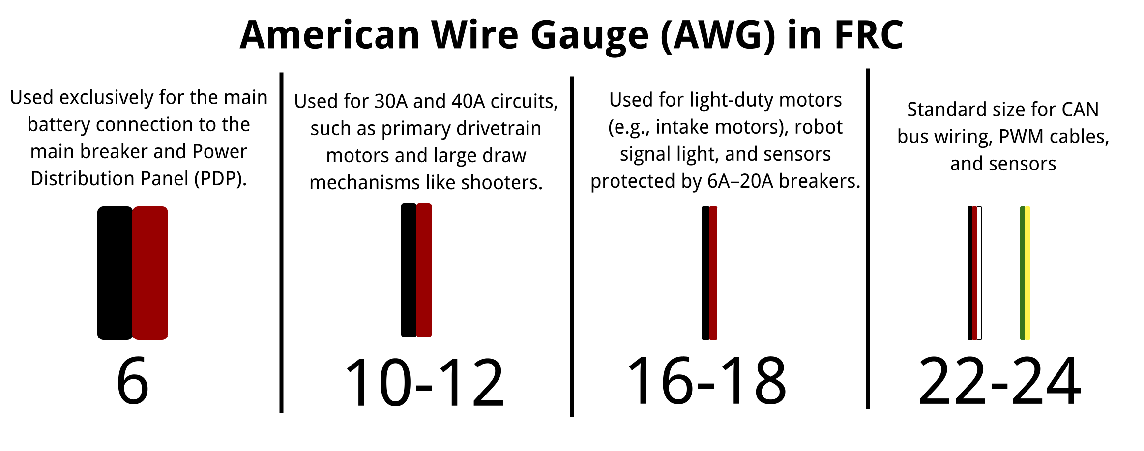
What does AWG mean?
AWG stands for American Wire Gauge. It is a sizing system for wire. The smaller the AWG number, the thicker the wire.
Always confirm exact wire gauge and breaker requirements with the current FRC rules and device documentation.
In FRC, the connector type should match the current level, the device, and how often the connection may need to be serviced.

Anderson Connector
Used for the main robot battery connection. This is a high-current connector and is part of the robot’s main power path.
- Used on battery leads
- Must be crimped well
- Loose power connections cause major failures
PWM/Signal/CAN Connectors
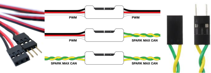
Small 2 and 3 wire or specialized connectors used for CAN devices, sensors, and low-current connections.
- Carry signal and low power
- CAN wires are usually yellow/green twisted pair
- Easy to unplug if not secured with clips
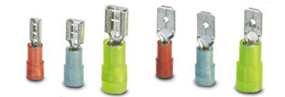
Crimp Terminals
Crimp terminals are commonly used for connecting wires to screw terminals, motor controllers, breakers, grounding points, and other electrical hardware.
- Available in different sizes for different wire gauges
- Must match both the wire size and terminal shape
- Need a proper crimping tool
- A bad crimp can pull out or heat up
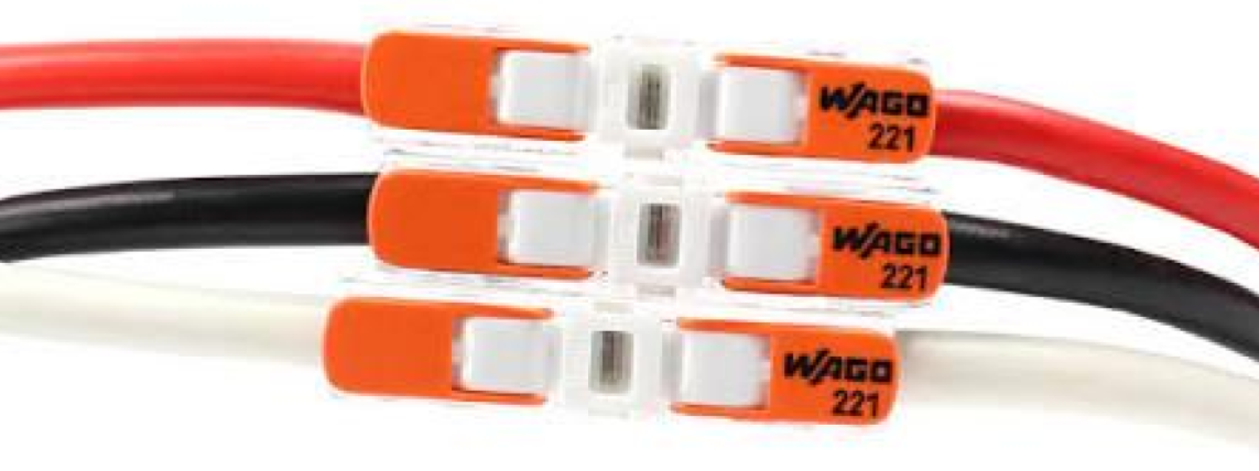
Lever/Wago Connectors
Lever-style connectors are useful in many electrical contexts because they are fast and easy to service. Always verify whether a given connector is appropriate for the current level and current FRC rules.
- Quick to connect and disconnect
- Helpful for low-current service or test connections
- Should not replace proper high-current terminals
- Always check rules and manufacturer ratings
1. Strip correctly
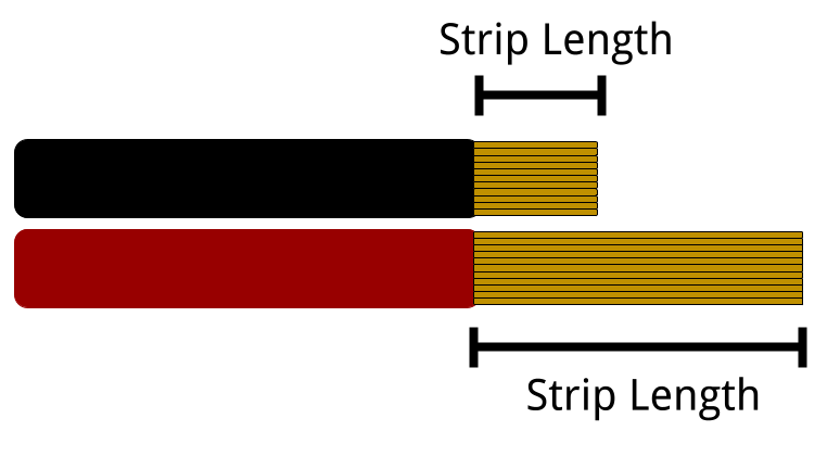
- Use the correct stripping slot for the wire gauge
- Be careful to only remove insulation
- Twist strands lightly only if needed to keep them together
2. Crimp correctly
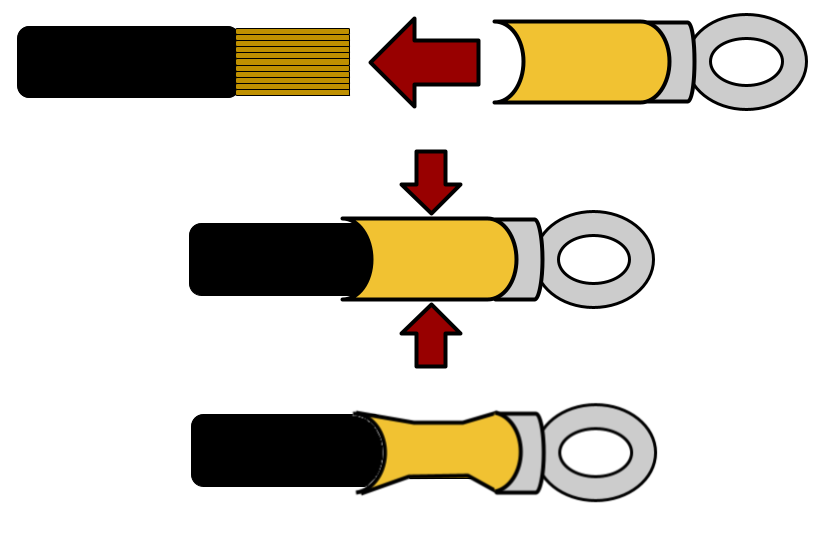
- Match terminal size to the wire gauge
- Place the crimp tool on the metal barrel, not just the plastic sleeve
- Tug-test every crimped connection
Good Practice: A clean strip and a solid crimp make the connection safer, stronger, and more reliable. Good wiring makes connections that survive vibration, impacts, and repeated maintenance.Many robot failures in FRC are caused by wiring issues.

Every crimp should survive a firm tug test. A connection that fails in your hand will fail faster on a moving robot.
Wires should be documented, labeled, and routed such that you can trace the main electrical path from the battery to the components on the robot.
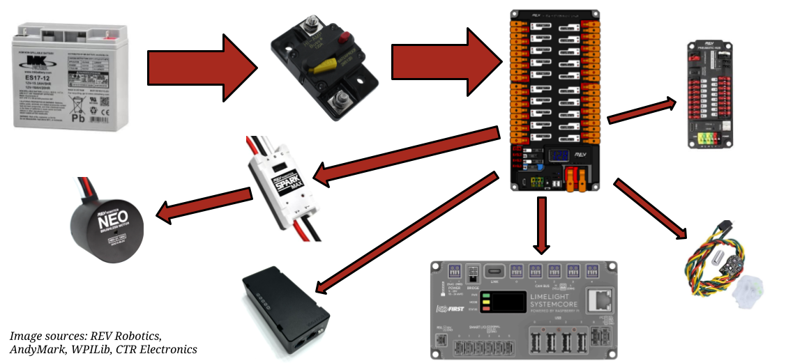
If you can trace where power goes, you can troubleshoot it quicker.
Keep wires safe before the robot moves
Do
- Use the correct wire gauge for the circuit and breaker.
- Keep battery cables short, protected, and secured.
- Use strain relief so wires do not pull out during impacts.
- Protect wires with grommets or edge protection.
Avoid
- Chains, gears, belts, shooters, and intakes.
- Sharp metal edges and pinch points.
- Wires crossing pivots without slack or protection.
- Loose wiring near wheels or the floor.
Organize wiring so people can understand it
Traceable
Bundle wires neatly, but do not make them impossible to follow.
Labeled
Label both ends of important wires and use consistent wire colors.
Accessible
Keep electronics, motor controllers, status lights, and ports reachable.
Design for the pit: someone should be able to diagnose a problem under time pressure without cutting every zip tie off the robot.
Wire covering helps prevent shorts, abrasion, snags, and damage from impacts or repeated motion. In FRC, wire protection is especially important anywhere wires run near sharp edges, mechanisms, bumpers, game pieces, or moving subsystems.
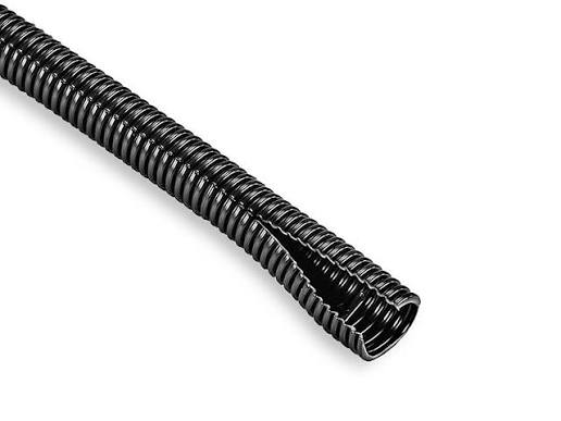
Split Loom
Corrugated plastic tubing used to protect bundles from rubbing and impact.
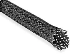
Braided Sleeve
Flexible woven sleeve that gives long wire runs a clean, protected finish.
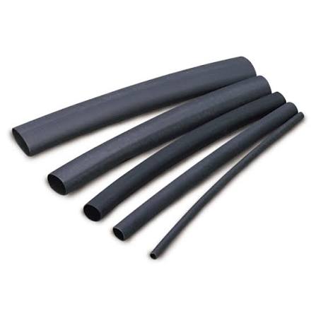
Heat Shrink
Used on joints, labels, terminal ends, and other small protected areas.

Electrical Tape
Useful for temporary labeling or minor insulation, but not ideal as the main long-term wire bundle solution.
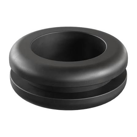
Grommets
Protect wires when they pass through holes in metal, polycarbonate, or other panels.
Goal: Covering should protect wires without making them impossible to inspect, trace, or repair.
Best uses
- Split loom: good for general wire bundles exposed to rubbing or impacts.
- Braided sleeving: good for longer visible wire runs where a clean look matters.
- Heat shrink: best for small exposed spots, labels, joints, and terminal strain relief.
- Grommets: required wherever wires pass through sharp-edged holes.
- Electrical tape: okay for temporary marking or light-duty insulation, not as the main protection system.
Key FRC reminders
- Protection should prevent rubbing on metal, bumpers, belts, chains, wheels, and gears.
- Do not bury important wires so deeply that students cannot troubleshoot them in the pit.
- Use protection that still allows you to service the robot quickly.
- Moving mechanisms usually need both protection and controlled routing.
- Good protection reduces failures from vibration, impacts, and repeated maintenance.
Passing through a panel
Use a grommet or edge protection.
At a terminal or joint
Use heat shrink for insulation and strain relief.
For long visible runs
Use braided sleeve or split loom.

Zip Ties
Most common way to secure wires to the frame or in bundles.
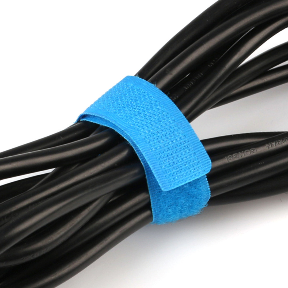
Velcro Ties
Better where wires need to be reopened often for service or troubleshooting.

P-Clamps
Stronger, screw-mounted support for heavy wire bundles or important power runs.

Cable Chain
Controls the bend path for moving wires on elevators, arms, intakes, or turrets.
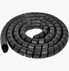
Spiral Wrap
Protects bundles while still letting you break out individual wires.
Good habits
- Bundle wires so they are neat and traceable.
- Support heavier power wiring more strongly than light signal wiring.
- Do not crush small wires or pinch CAN pairs with overtightened zip ties.
- Keep connectors accessible for repairs.
Common mistakes
- Wires crossing messy paths between mechanisms.
- Loose loops that can snag in motion systems.
- No support near connectors.
- Using only adhesive mounts in high-vibration areas.
Why slack matters
- Wires need enough slack to allow full mechanism motion without pulling on connectors.
- Service loops make it easier to remove a motor controller, radio, or controller for repairs.
- Without slack, vibration and motion can loosen terminals or break conductors over time.
- Too much slack is also a problem because it can snag in belts, chains, gears, wheels, or intakes.
Best practice for slack
- Leave a small, controlled service loop near important devices.
- On moving subsystems, route slack through a predictable bend path.
- Use cable chain, loom, or guided routing where motion repeats often.
- Secure the wire before and after the moving section so the connector itself is not the stress point.
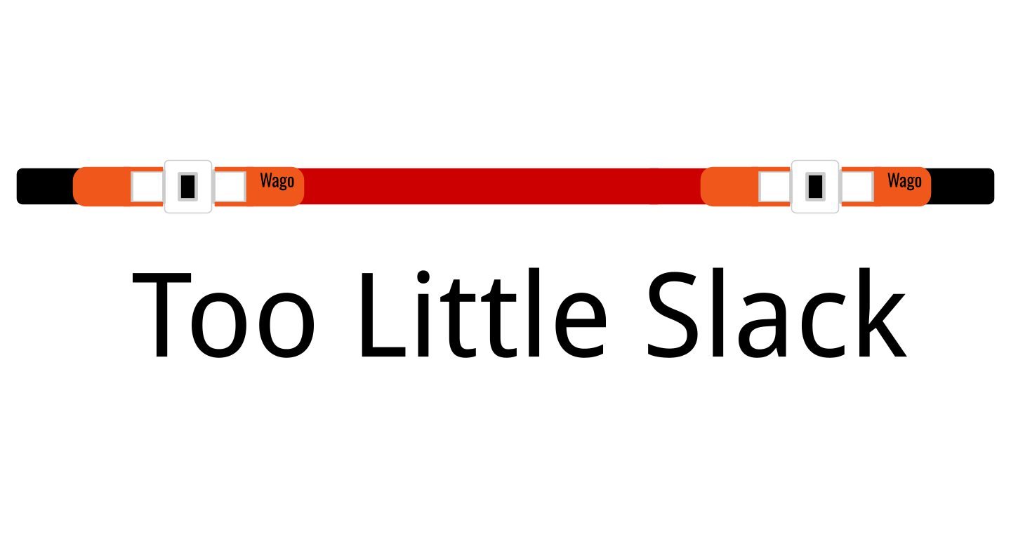
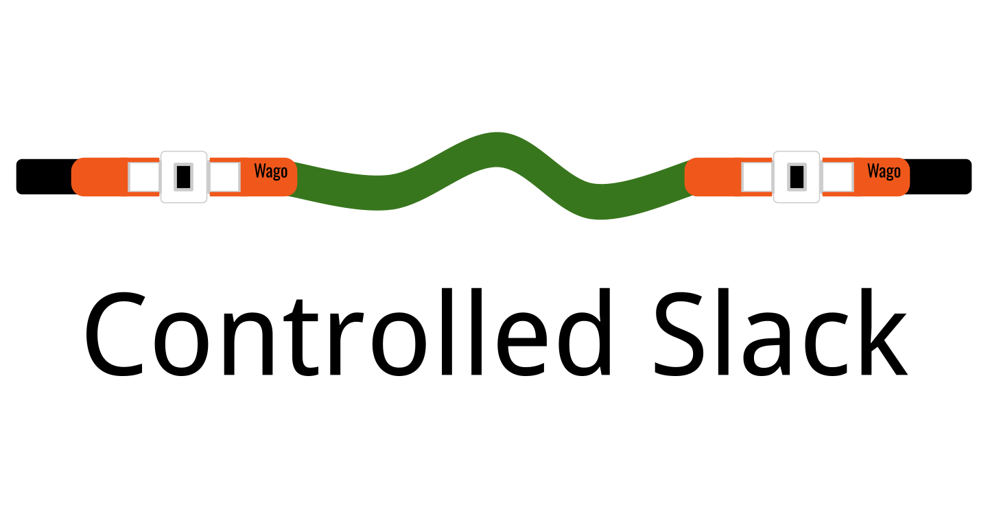

Student rule: Leave enough slack for motion and service, but not enough to become a hazard.
What Good Wiring Looks Like
Wire Management Checklist
- Wires are secured and do not flop loosely.
- Bundles are protected with loom, braid, or other covering where needed.
- Wires are kept away from chains, belts, gears, wheels, and sharp edges.
- Grommets or edge protection are used when wires pass through holes.
- Connectors are accessible for troubleshooting and pit repairs.
- Moving mechanisms have controlled slack or cable chain routing.
- Wires are labeled or color-managed so students can trace them quickly.
- The wiring looks intentional, serviceable, and match-ready.
In Short: Secure it, protect it, label it, and make sure you can fix it.
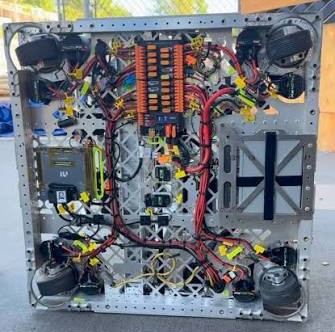
Example: Team 3255 Robot Wiring
Small wires still need protection
Mount firmly
A sensor that moves during a match gives bad data even if it is wired correctly.
Protect cables
Sensor wires are often small and easy to damage near arms, elevators, intakes, and game pieces.
Label inputs
Documentation helps programmers and pit students know which signal is which.
Power Wire Example

- Shows where power starts.
- Shows what device it feeds.
- Helps find the correct breaker.
Note: There is no one way to do this and this example is illustrate one way to track wiring.
CAN Wire Example
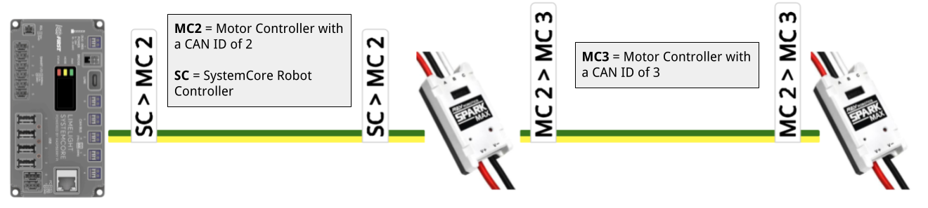
- Shows device CAN IDs.
- Shows device connections.
- Helps debug missing devices.
Keep it simple:The best label is short, readable, consistent, and matches the documentation.
Simple Wiring Table

Tip: Use the same device names in labels, code, CAD notes, and pit documentation.
“The robot turned on” is not enough
A battery can power the robot in the pit and still be a poor choice for a match.
- Charge batteries properly.
- Label batteries.
- Track battery age and performance.
- Inspect battery terminals.
- Make sure battery lugs are tight.
- Cover exposed terminals.
- Use a proper battery cart or safe storage.
- Secure the battery firmly in the robot.
- Never allow the battery to fall out during a match.
- Retire weak or damaged batteries from competition use.
Fast questions before the robot leaves the pit
Charge
Is this battery fully charged and known to perform well under load?
Condition
Are terminals tight, covered, clean, and undamaged?
Retention
Is the battery fully secured in the robot before the match?
Use a systematic order
When a robot does not work, do not randomly unplug and replug things. Work from the simplest and most central checks outward.
Start with basics
Battery, breaker, roboRIO, radio, Driver Station connection, and motor controller power.
Then go deeper
CAN visibility, faults, brownout logs, mechanism motion, and what changed since it last worked.
Students should get comfortable using:
Driver Station Logs
Voltage, packet loss, brownouts, and match timing clues.
Status Lights
roboRIO, radio, and motor controller LEDs can quickly narrow problems.
Vendor Tools
REV Hardware Client or vendor tools for IDs, firmware, faults, and device status.
Multimeter + Load Tester
Verify voltage, continuity, and battery health instead of guessing.
Pass to complete the module
Each question is on its own slide.
Answer all 20 questions, then grade the quiz. Score at least 18 out of 20 to unlock the completion slide.
Grade the quiz
You need at least 18 out of 20 to unlock completion.
Not submitted.
After passing, advance to the final completion slide.
Wire it right.
5041 CyBear Robotics
Complete after passing the required quiz.