
General Robot Design Training Module

Module Goals

By the end, students should be able to:

  • Follow a general process for structural design.
  • Explain the difference between strength and stiffness.
  • Understand the importance of weight distribution.
  • Understand the difference between stiffness and strength.
  • Understand what a load paths through a robot frame or mechanism is.
  • Choose fabrication methods that match team tools and time.
  • Design for bumpers, wiring, maintenance, and impact before final build.
  • Use CAD as a communication, design, and documentation tool.
General Design Checklist
  • Does the robot meet geometric and weight constraints?
  • Are loads supported by strong frame members instead of small brackets?
  • Are arms, elevators, climbers, and intakes mounted securely?
  • Is the frame rigid and square?
  • Is the center of gravity low enough for stable driving and scoring?
  • Can we build this accurately with our available tools?
  • Do bumpers mount securely and meet requirements?
  • Are extensions impact durable?
  • Are electronics and impact sensitive equipment in protected spaces?
  • Does the design allow for accessibility and repair?
  • Does the design include consideration for wire placement and management?
  • Does the design have good documentation and testing?

Get into the habit to ask these before CAD is “done”, before parts are cut, and again before competition.

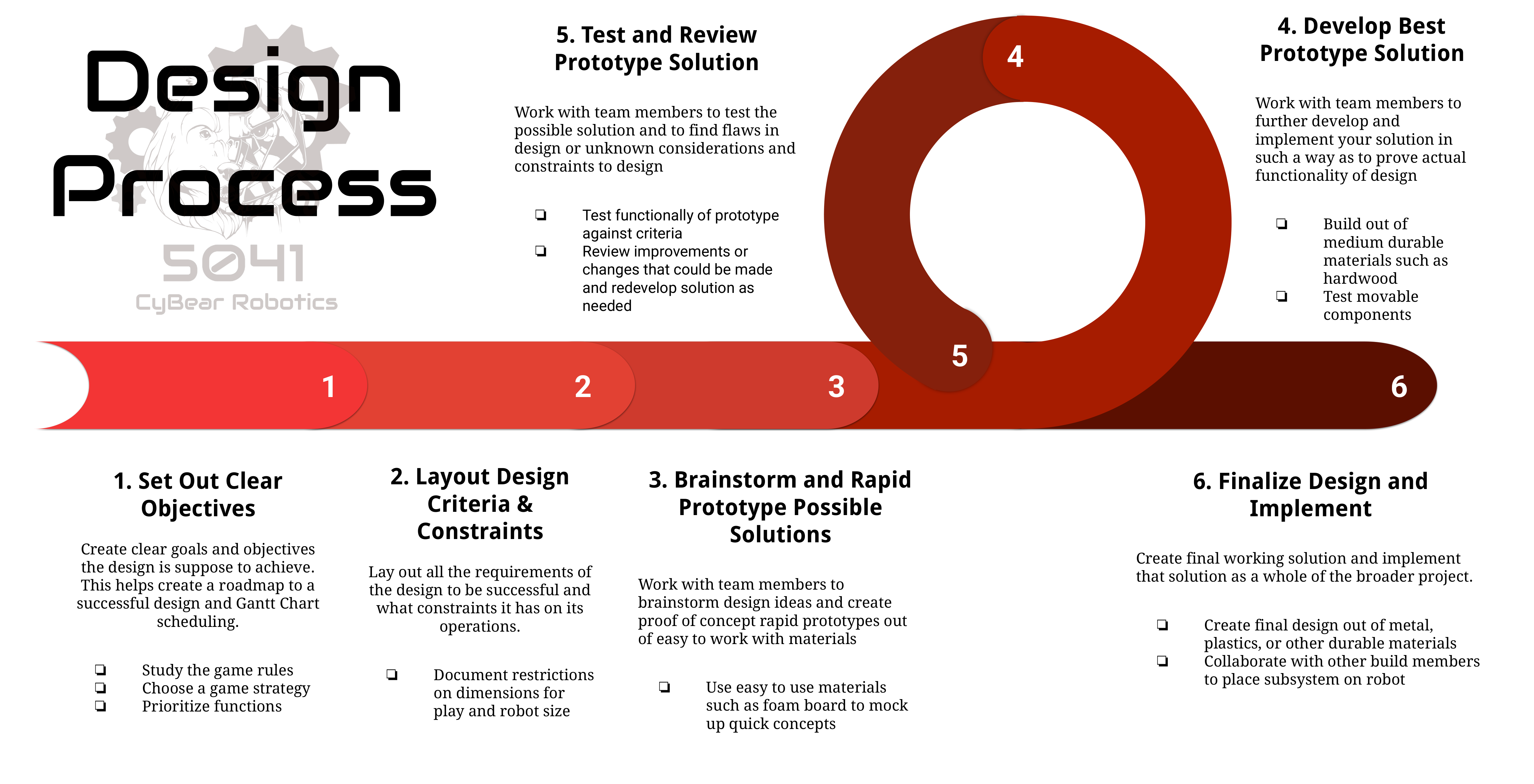
5041 Design Process

Use the team process before expensive material is cut

1. Set Out Clear Objectives
2. Layout Design Criteria & Constraints
3. Brainstorm & Rapid Prototype
4. Develop Best Prototype
5. Test & Review Prototype
6. Finalize & Implement

This means using cheap and quick prototypes and CAD to answer overall spacing, movement, and placement questions, then moving into CAD and durable materials after the design has been decided.

5041 Design Process Poster

Team process reference

5041 Design Process Poster with six steps

Steps 1–2: Objectives, criteria, and constraints

1. Set Out Clear Objectives

Create clear goals and objectives. Study the game rules, choose a game strategy, and prioritize functions.

2. Layout Design Criteria & Constraints

Document requirements and restrictions, including play dimensions, robot size, frame perimeter, bumper rules, and field/game piece needs.

Steps 3–4: Prototype possible solutions

3. Brainstorm and Rapid Prototype

Create proof-of-concept prototypes from easy-to-work materials such as foam board, cardboard, scrap wood, or spare tube.

4. Develop Best Prototype

Build the strongest candidate from medium-durable materials such as hardwood or better test parts, then test movable components.

Steps 5–6: Test, finalize, and implement

5. Test and Review Prototype

Test against criteria, find flaws, identify new constraints, and redevelop the solution as needed.

6. Finalize Design and Implement

Create the final version from durable materials such as metal or plastics, then collaborate with build members to place the subsystem on the robot.

5041 Design Process

Put the design process in the correct order

Brainstorm & Rapid Prototype
Finalize & Implement
Set Out Clear Objectives
Test & Review Prototype
Layout Design Criteria & Constraints
Develop Best Prototype
CAD, CAD, CAD

CAD should answer practical questions and document design

CAD has a lot of uses. It can:

  • check dimensions
  • check field constraints
  • determine mechanism travel
  • determine bumper placement
  • determine electronics & battery location
  • act as an iterative prototyping platform
  • act as validation before fabrication starts
CAD Basics

What is CAD?

Computer-aided design technical drawing

CAD stands for Computer-Aided Design. It is software used to create accurate digital models of parts, assemblies, and mechanisms before they are built in real life.

  • Create accurate 2D sketches and 3D parts
  • Assemble parts into mechanisms or full robots
  • Check dimensions, spacing, and fit
  • Share designs before fabrication

Team 5041 uses Onshape as its main CAD program. Onshape is browser-based, so students can work on robot designs from school computers, personal laptops, or Chromebooks without installing large software.

Because OnShape saves work online, multiple students and mentors can view, edit, and comment on the same robot design as it develops.

  • Runs in a web browser
  • Allows team collaboration in shared documents
  • Keeps version history as designs change
  • Creates parts, assemblies, and drawings for fabrication

Logo: Conrado.arias, CC BY-SA 4.0, via Wikimedia Commons

CAD and Geometric Contraints

Mechanisms do not move in empty space. In FRC they have to work around the game piece, the field elements, and the robot's own components. CAD lets us mock up those relationships for better design.

Some examples of this are:

  • Checking how far an elevator must travel
  • Finding the range of motion of manipulators
  • Finding possible collisions with field elements
  • Confirming the game piece can enter, move, and release cleanly
  • Comparing positions for different scoring possibilities

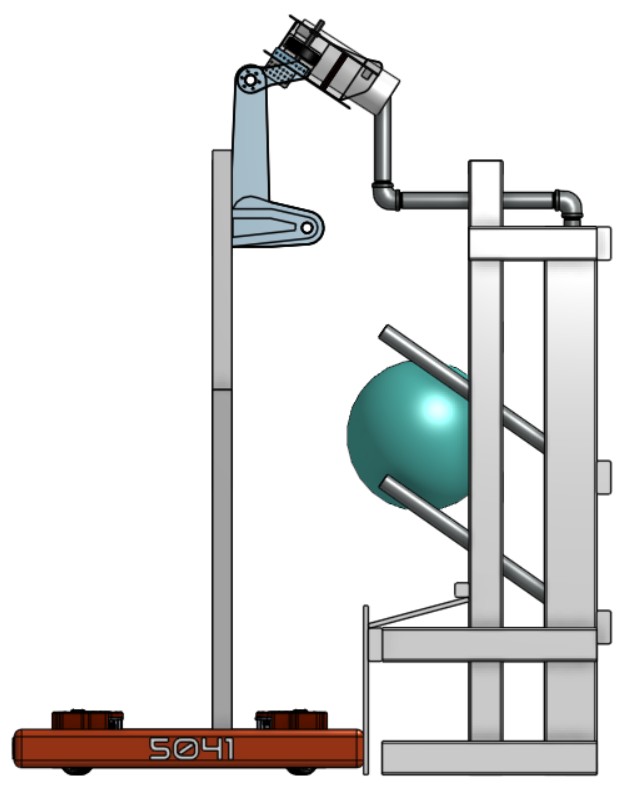
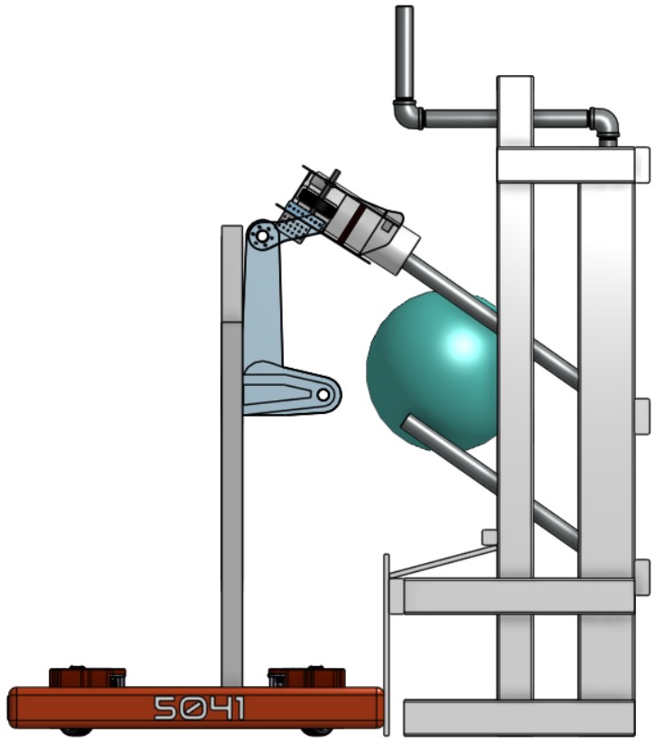
In REEFSCAPE, 5041 used CAD to study how high Ursula's elevator needed to lift and what angle the coral arm needed to reach so coral could be deposited onto the reef.

Ursula depositing coral at a higher reef level
Higher reef level: elevator extension and arm angle both change.
Ursula depositing coral at a lower reef level
Lower reef level: same mechanism, different geometry.
CAD as a Prototyping Platform

CAD is not just for final robot designs. It is a place to test ideas, compare versions, and improve parts before they are built.

  • Change geometry quickly
  • Compare multiple versions of the same part
  • Find weak points or awkward dimensions early
  • Move from rough prototypes toward final parts
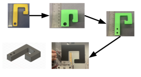
Iterations of Bearthoven's 2024 climber hook design
5041's 2024 robot Bearthoven's climber hook changed through several versions as the team tested shape, size, mounting holes, and how the hook interacted with the chain.
Precision Design

When CAD is paired with advanced manufacturing, teams can design parts with exact hole spacing, gear placement, bearing locations, and material thickness in mind.

  • Place shafts, gears, and bearings accurately
  • Design around real material thickness
  • Create parts for CNC routers, laser cutters, 3D printers, or mills
  • Reduce guesswork during fabrication and assembly
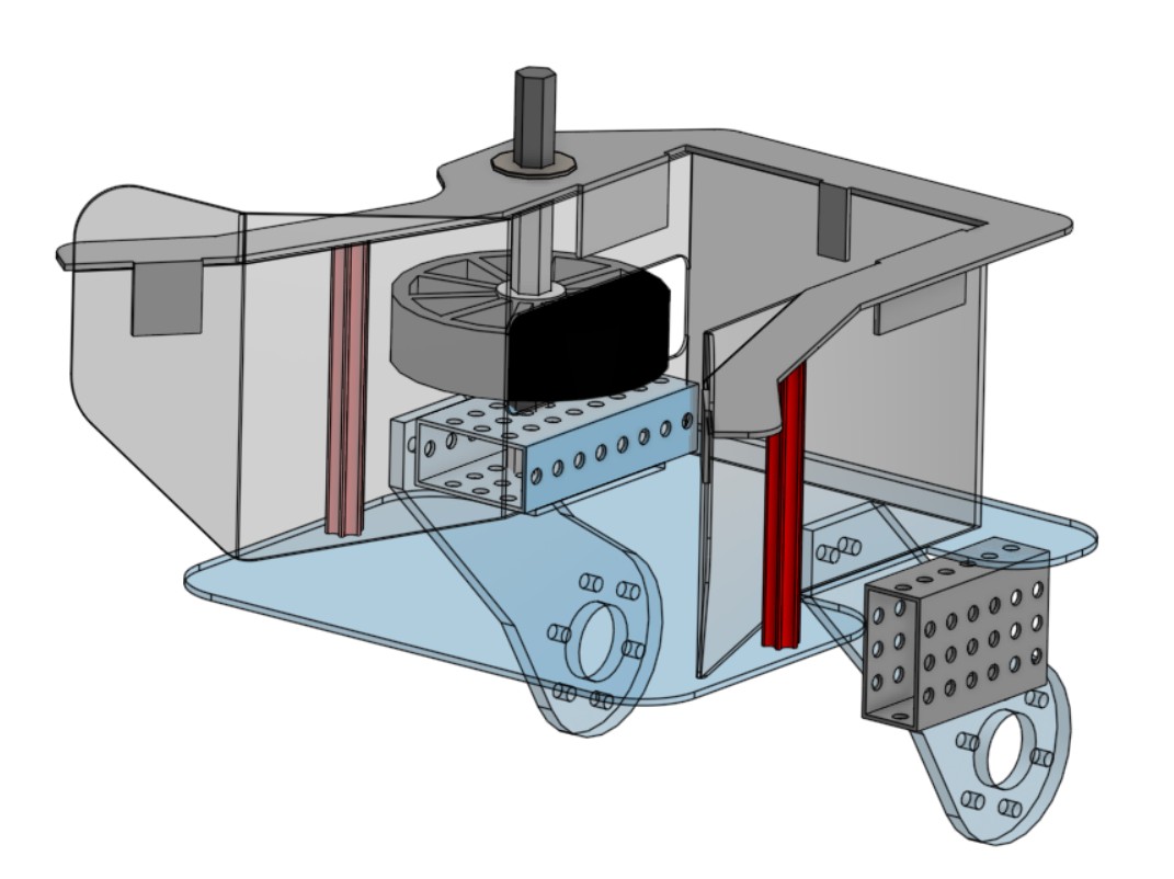
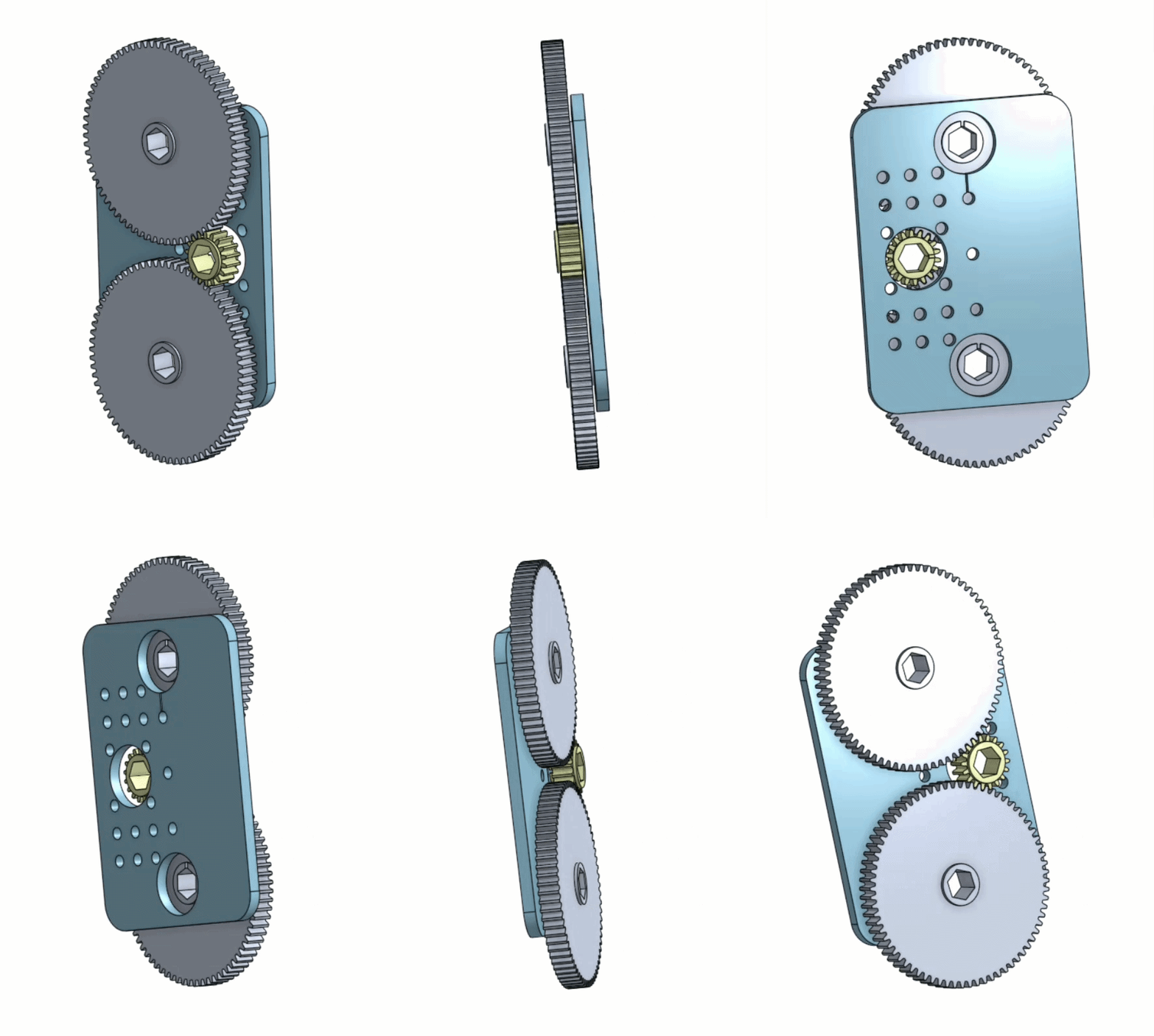
CAD animation of Kuruk's 2026 polycarbonate gearbox
5041's 2026 robot Kuruk's polycarbonate gearbox shows how CAD can define exact geometry before a part is manufactured from sheet material.
Robot Documentation

CAD also creates a record of what the team built and why. Drawings, dimensions, and saved assemblies help students explain the design and improve it later.

  • Record important dimensions
  • Show mechanism positions and clearances
  • Help new students understand past robots
  • Create references for repairs, upgrades, and future designs
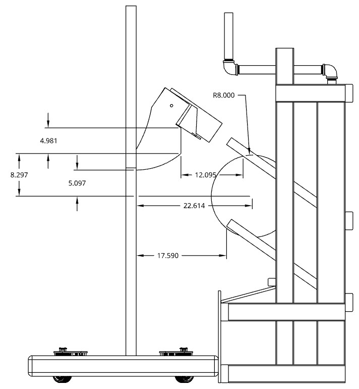
Dimensioned CAD drawing of Ursula's 2025 robot scoring geometry
5041's 2025 robot Ursula's drawing document shows the robot-to-reef geometry, including distances, clearances, and scoring position.
CAD Next Steps

To begin learning CAD, create an Onshape Education account and then bookmark the FRC Design learning course to build skills with robot-specific examples.

1. Create an Onshape Account

Onshape is the browser-based CAD program used by 5041. Students can use the free Education Plan to model parts, assemblies, and robot mechanisms. Use your school email.

Onshape Education Sign-Up

2. Continue With FRC Design

FRCDesign.org has a guided CAD learning course focused on Onshape and robot design fundamentals for FIRST Robotics Competition. Bookmark the link below.

FRC Design Learning Course
Frame First

Start with the frame and load paths

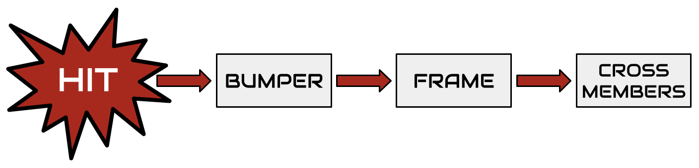
“When it gets hit, where does the force go?”

Force Flow Chart

If the path includes “through a tiny bracket,” redesign it.

Impact Direction Matters

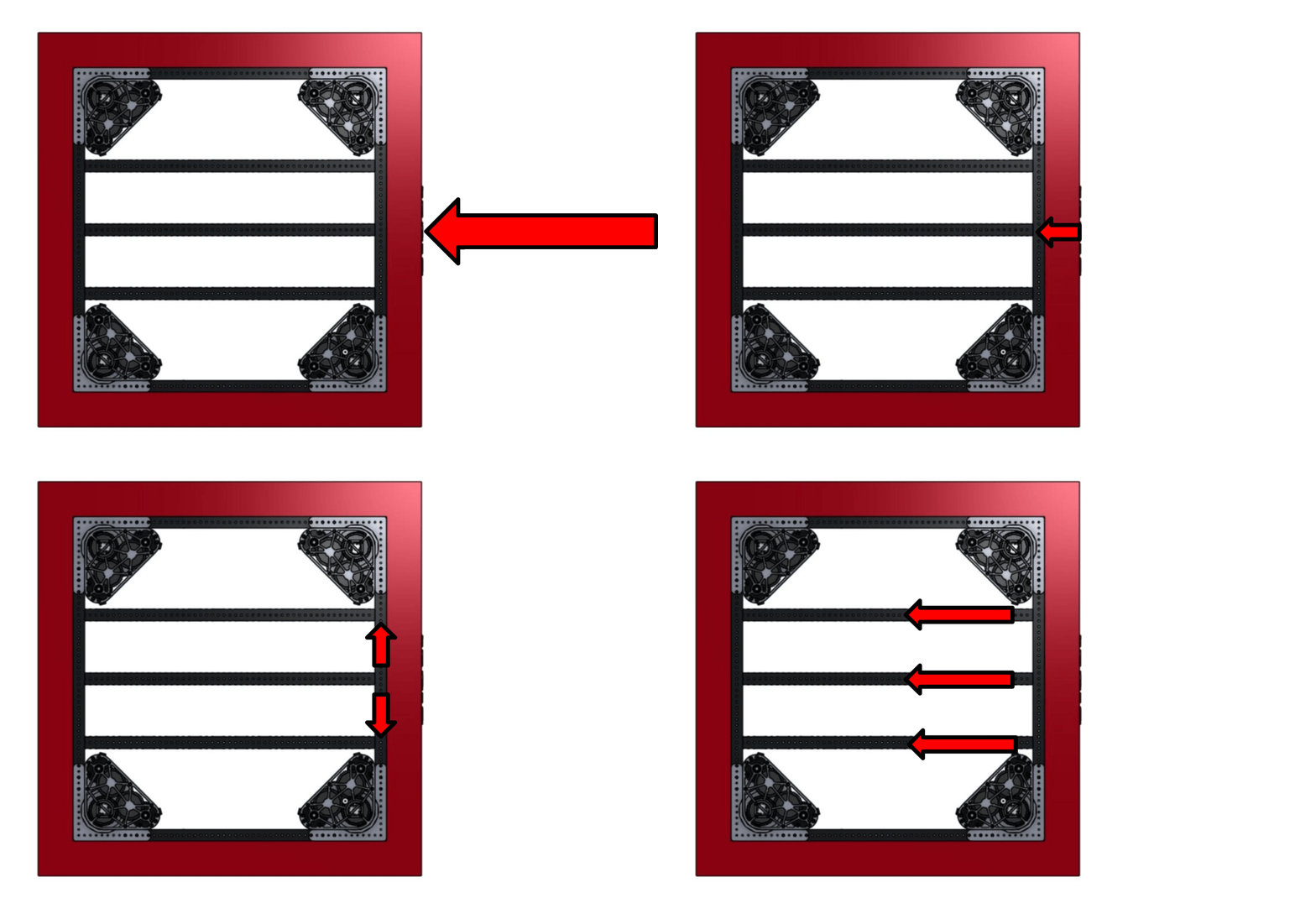
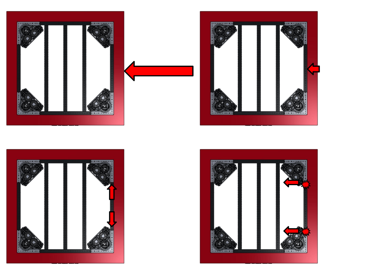
FRC robots take hits from many directions. A structure may handle one impact direction well but be weaker from another direction depending on how the frame members are arranged.

Front Impact: Better Load Distribution

Front impact on FRC robot frame
The force travels into several long frame members, spreading the load across more of the structure.

Side Impact: Less Support

Side impact on FRC robot frame
The force pushes across fewer supporting members, making bending or twisting more likely.

Frame Design Rules of Thumb

Drag each card into the correct category: Do or Avoid.

Small brackets carrying major loads.
Keep the frame square.
Heavy mechanisms on weak supports.
Use crossmembers and gussets.
Last minute bumper mounts.
Mount bumpers early in the design.
Forcing misaligned parts together.
Route forces through strong members.
Thin-walled metals and weak 3D printed parts in high-load areas.
Use appropriately strong materials.

Do

Avoid

Strength and Stiffness

Strength = Not Breaking. Stiffness = Accuracy.

Strong parts do not always make an accurate robot. A part can survive and still flex enough to miss shots, bind an elevator, or throw off alignment.

Strength vs. Stiffness

Strength

Strength is whether a part can survive the load without permanently bending, cracking, or breaking.

Stiffness

Stiffness is how much a part resists flexing while it is being loaded. A part can be strong enough but still too bendy to work well.

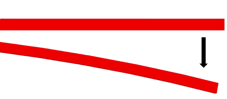
Cantilever beam deflection diagram
A beam may not break, but too much deflection can still cause problems.
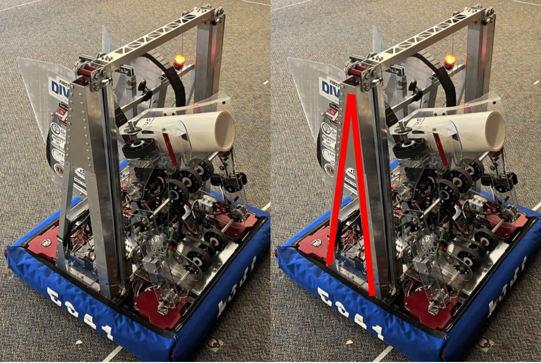
Ursula triangle support structure
Trusses add stiffness by spreading loads through triangles.

Areas that need stiffness

Shooters

Consistent angle and wheel spacing.

Elevators / Arms

Parallel rails, stable pivots, hard stops.

Vision / Sensors

No wobble, protected mounting.

Swerve / Drivetrain

Square frame and rigid module mounts.

Belts / Chains

Aligned shafts and tension control.

Climbers

Loads travel into the frame, not thin side plates.

Stiffness quick fixes

  • Shorten unsupported spans.
  • Add triangles: gussets, diagonal bracing, boxed structures.
  • Use tube instead of flat plate where possible.
  • Support shafts on both sides.
  • Use hard stops instead of relying on motor limits alone.
Robot Weight

Weight is a constraint for FRC robots and distribution affects how an FRC robot drives, turns, accelerates, scores, and survives defense. A robot can have strong mechanisms but still perform poorly or be over limits.

Stability

Heavy parts mounted high can make the robot tip when accelerating, turning, climbing, or reaching.

Driving

Too much weight on one side, front, or back can reduce traction and make the robot harder to control.

Scoring Accuracy

Moving arms, elevators, and game pieces can shift the center of mass and change how the robot behaves.

Weight Dos and Donts

Do

  • Mount heavy components low.
  • Consider how moving components shift weight.
  • Use as light materials as possible.

Avoid

  • Putting too much mass in any one direction.
  • Adding thick material everywhere “just to be safe.”
  • Ignoring weight until finished.

For swerve drivetrains, uneven weight distribution can affect wheel loading, traction, steering consistency, and how predictably the robot drives.

Interactive Balance Challenge

Drag the masses around the robot frame. Try to place the center of mass near the center line.

Center Line
COM
Battery
12 kg
Gearbox
8 kg
Elevator
10 kg
Intake
6 kg
Left Heavy Balanced Right Heavy
Impact + Repair

Prepare for Impacts, Design for Repair

FRC robots should be designed with the assumption that they will be hit, pushed, dropped, tangled, and repaired quickly between matches.

Prepare for Impacts

Protect the parts that keep the robot driving, scoring, and communicating.

Design for Repair

Make common failures fast to inspect, remove, replace, and test.

A strong robot is not just hard to break. It is also easy to fix.

Impact Preparation

Protect Important Parts

Protect

  • Exposed wheels
  • Belts and chains
  • Wires and pneumatic tubes
  • Sensors and cameras
  • Fragile mechanisms

Avoid

  • Long, thin, unsupported parts sticking out
  • Fragile parts outside the frame perimeter
  • Mechanisms that can overtravel
  • Loose or weak bumper mounts

Keep fragile mechanisms inside the frame perimeter when possible.

Impact Design Choices

Strong, Flexible, or Replaceable

Strong

Use strong materials, gussets, hard stops, and secure mounts where parts must survive impacts.

Flexible

Let intakes or touch points flex when they contact game pieces, robots, or field elements.

Replaceable

Design exposed parts so they can be swapped quickly with simple tools and spare parts.

Good rule: Anything outside the frame perimeter should be strong, flexible, or easy to replace.

Maintenance Access

Make Maintenance Easy

Design Choices That Help

  • Easy battery access
  • Easy main breaker access
  • Accessible motor controllers
  • Removable panels
  • Clear wire paths

Prepare for Competition

  • Replaceable intake parts
  • Spare gussets and brackets
  • Standardized bolts and rivets
  • Labeled wires and pneumatic tubes
  • Parts that can be reached with normal tools

Ask during design review: Can we fix this in five minutes between matches?

Required Quiz

Pass to complete the module

Each question is now on its own slide.

Answer all 20 questions, then grade the quiz. Score at least 18 out of 20 to unlock the completion slide.

Quiz Question 1
1 of 20

What is the main purpose of a general robot design checklist?

Quiz Question 2
2 of 20

Which question best represents load path thinking?

Quiz Question 3
3 of 20

In the 5041 design process, what should happen first?

Quiz Question 4
4 of 20

Which of these belongs in the “criteria and constraints” step?

Quiz Question 5
5 of 20

Why should teams prototype before committing to a final design?

Quiz Question 6
6 of 20

What is CAD especially useful for before fabrication begins?

Quiz Question 7
7 of 20

Why does Team 5041 use Onshape?

Quiz Question 8
8 of 20

In REEFSCAPE, what could CAD help determine for Ursula’s coral scoring mechanism?

Quiz Question 9
9 of 20

What is strength?

Quiz Question 10
10 of 20

What is stiffness?

Quiz Question 11
11 of 20

A shooter mount does not break, but it flexes enough to miss shots. What is the main issue?

Quiz Question 12
12 of 20

Which robot areas especially need stiffness?

Quiz Question 13
13 of 20

Which design choice helps improve stiffness?

Quiz Question 14
14 of 20

Which is a good frame design habit?

Quiz Question 15
15 of 20

Why should bumper mounting be designed early?

Quiz Question 16
16 of 20

Which is a good rule for parts outside the frame perimeter?

Quiz Question 17
17 of 20

What should be protected from impacts?

Quiz Question 18
18 of 20

What is a good weight distribution goal?

Quiz Question 19
19 of 20

Why can poor weight distribution hurt a swerve drivetrain?

Quiz Question 20
20 of 20

What should a subsystem lead be able to show before fabrication approval?

Quiz Results

Grade the quiz

You need at least 18 out of 20 to unlock completion.

Not submitted.

After passing, advance to the final completion slide.

Build it right.

Strong • Stiff • Light • Accurate • Repairable

5041 CyBear Robotics

Complete after passing the required quiz.